
MarSurf 3d
Non-Contact Surface Topography Analysis
What MarSurf 3D is
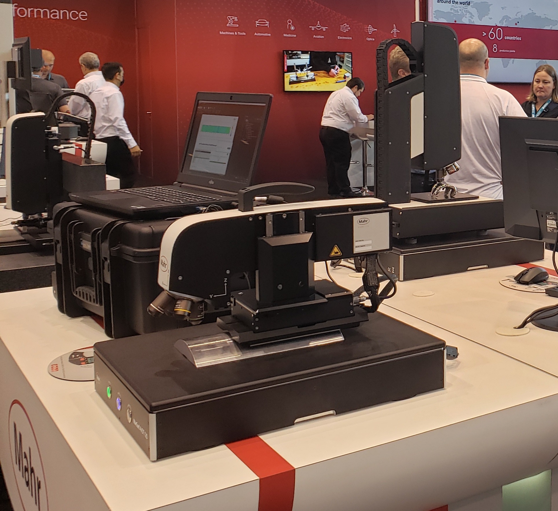
MarSurf 3D is Mahr's family of optical, non-contact instruments for measuring surface texture over an area. A stylus roughness gage traces one line across the part and reports profile parameters such as Ra (roughness average). A MarSurf 3D instrument records a height value at every pixel in its field of view and builds a 3D map of the surface. Parameters calculated from that map are areal, or surface, parameters, defined in ISO 25178.
The line consists of:
- Sensors: the optical measuring units. The MS multisensor combines confocal, white light interferometry and focus variation. Single-technology confocal (CM) and interferometer (WI) sensors and chromatic profilometers (CP, CL) are also available.
- Platforms: the MarSurf3D SX bench-top and GS portal stands, which hold the part and move it under the sensor.
- CM mobile: a portable confocal system for parts too large to bring to the instrument.
- Evaluation software: MarSurf3D software, common to all sensors on the SX and GS.
MarSurf 3D is used in the lab and in quality assurance on surfaces whose texture affects function. Mahr's application examples include sealing faces on electric-drive housings, fuel-cell bipolar plates, implants, micro-optics, printed electronics, textured consumer surfaces, rolled steel sheet and additively manufactured parts. Nothing touches the part, so soft, coated and finished surfaces can be measured without marking them.
Measured characteristics
- Areal roughness per ISO 25178 and ISO 13565
- Profile roughness per ISO 4287 and ISO 21920
- Flatness per ISO 12781
- Step height and layer thickness, including transparent layers
- Particles and pores: detection, classification, height, depth, area, volume and diameter
- Geometry and contour: radii, angles and distances
Profile and areal parameters
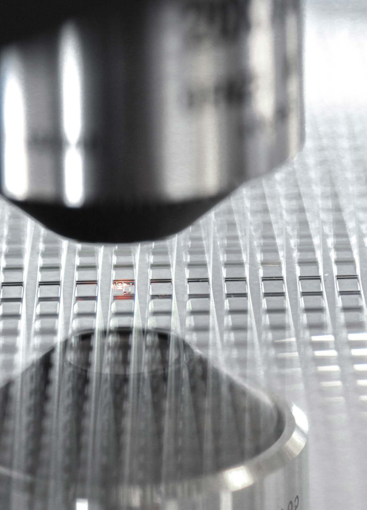
A profile parameter such as Ra describes one line across the surface. Anything the line misses does not appear in the result. An areal parameter such as Sa is calculated over the full measured area, so pits, scratches and the direction of the texture are all included.
Why an average is not enough
Ra and Sa are averages of the height deviation from the mean line or plane. Two surfaces can have the same average and behave very differently. A plateau surface with deep valleys, typical of a honed cylinder bore, carries load on the plateaus and holds oil in the valleys. The same profile turned upside down has sharp peaks that carry the load on small areas and wear first. Both have the same Ra.
The Sk family separates these cases. Sk is the core roughness depth, Spk the height of the peaks above the core, and Svk the depth of the valleys below it. The profile versions (Rk, Rpk, Rvk) are defined in ISO 13565 and the areal versions in ISO 25178. Skewness (Ssk) gives the same distinction as a single sign: negative for the plateau surface, positive for the peaked one.
MS multisensor
The MarSurf3D MS combines three areal measuring principles in one sensor: Mahr's patented multi-pinhole confocal, white light interferometry and focus variation. The principle is selected per measurement, so different surfaces on the same part can each be measured with the appropriate method without moving the part or changing instruments. All results are evaluated in the same software, with vertical resolution into the lower nanometer range.
Without a multisensor, a lab measuring varied surfaces needs a separate instrument for each principle. Mahr specifies the MS for laboratory, QA and at-machine use.
The three principles
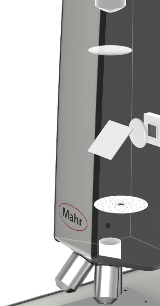
Light passes through a rotating multi-pinhole disc, and only the in-focus portion of the reflected light reaches the camera. A vertical scan gives a confocal curve per pixel, and its peak gives the height. The disc suppresses scattered light from neighboring points. Suited to structured and rough surfaces.
The objective splits light into a measuring beam and a reference beam. Their interference signal during a vertical scan gives the height of each pixel. Vertical resolution is subnanometer at any magnification. Suited to smooth, continuous surfaces and step heights.
Active lighting and a vertical scan find the height at which each pixel is in sharpest focus. Captures flanks inclined up to 86° and a large height range in one measurement. Suited to large, rough surfaces and steep features.
Mahr rates the three principles as follows:
| Surface or task | Confocal | Interferometry | Focus variation |
|---|---|---|---|
| Structured surfaces | Best | Good | Good |
| Rough surfaces | Best | Limited | Good |
| Smooth surfaces | Good | Best | Not suited |
| Steep flanks | Good | Limited | Best |
| Height measuring range | Good | Good | Best |
| Layer thickness | Good | Good | Not suited |
- One principle per sensor
- Appropriate where the parts measured are similar in surface type
- Available on all SX and GS configurations, including SX 3050
- Confocal, interferometry and focus variation from one measuring position
- Focus variation for steep flanks and tall features, not available on CM or WI
- One setup and one evaluation for mixed surfaces
- MS plus version with piezo drive for fine vertical scanning
- Available on SX 3100, 3200 and 3201 and on all GS configurations
Platforms
Platform selection follows part size and the required degree of automation. Both platforms accept the MS multisensor.
MarSurf3D SX
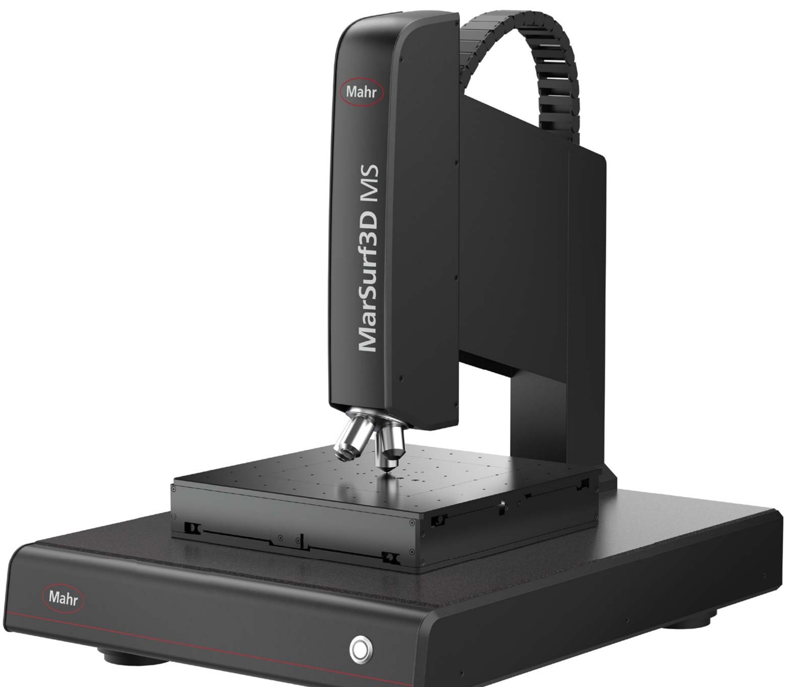
Compact platform for workpieces up to 200 mm (≈ 7.9"). Table travel 100 × 100 mm or 200 × 200 mm. Controller and damping are integrated in the base. HD stitching maintains full resolution across areas larger than one field of view. Accepts the CM, WI and MS sensors, and measurements can be automated.
Typical use: laboratory and QA measurement of parts that fit a bench-top stage.
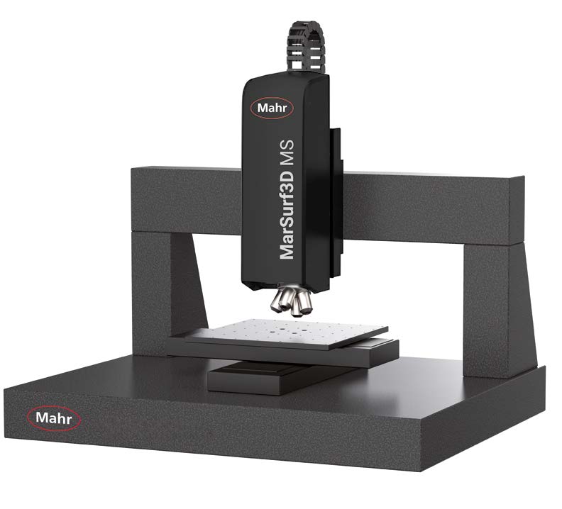
MarSurf3D GS
Portal platform for workpieces from 200 mm (≈ 7.9"). Axis sizes are selectable, with table travel from 200 × 200 mm to 450 × 450 mm (≈ 17.7"). Designed for continuous 24/7 operation. The only platform that accepts the CP and CL profilometer sensors. Options include an offset camera for setup and registration-mark detection, a point sensor and an enclosure.
Typical use: large or heavy parts, profilometry, and automated series measurement.
| Platform | Configuration | Sensors available |
|---|---|---|
| SX | 3050 | CM, CM plus, WI plus |
| SX | 3100, 3200, 3201 | CM, CM plus, WI plus, MS, MS plus |
| GS | 3201, 3300, 3301, 3501 | CM, CM plus, WI plus, MS, MS plus, CP, CL |
Single-technology and profilometer sensors
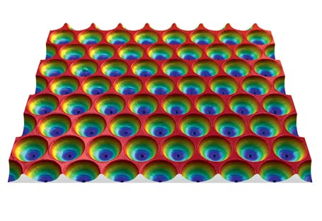
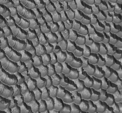
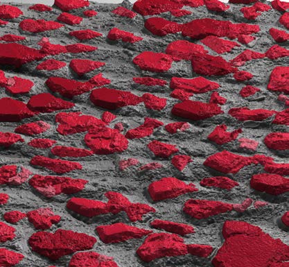
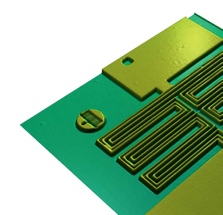
In addition to the MS multisensor, the platforms accept single-technology areal sensors and, on the GS, chromatic confocal profilometers. Plus versions add a piezo drive for fine vertical scanning. Images show typical measurement results for each principle.
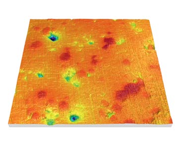
Confocal
Multi-pinhole confocal sensor. Covers smooth to very rough surfaces.
Best suited to: general areal measurement where interferometric resolution and steep-flank capability are not required.
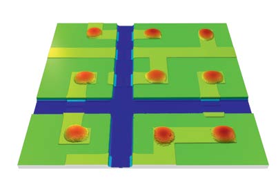
White light interferometry
Interferometric sensor with subnanometer vertical resolution at any magnification.
Best suited to: very smooth, continuous surfaces and nanometer-level step heights.
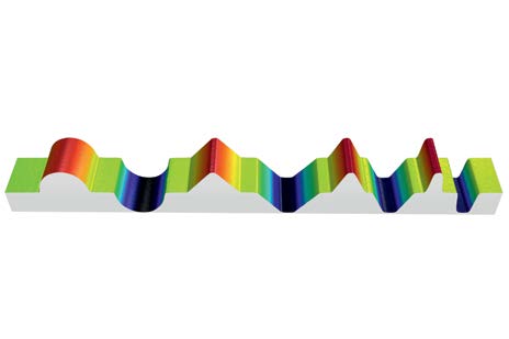
Chromatic point sensor
White light is split into wavelengths, each focused at a different height. A spectrometer identifies the in-focus wavelength, which gives the height. The point is scanned to build profiles and areas.
Best suited to: line roughness, height profiles, flatness and layer thickness over long travels, and features millimeters tall.
Chromatic line sensor
The chromatic principle applied to 192 points along a line, recording 192 parallel profiles per pass. Large areas are captured in seconds. Measures transparent materials and layer thickness.
Best suited to: large-area measurement where throughput matters more than microscope-level lateral resolution.
Feature heights by principle
Each principle covers a different range of feature heights. Interferometry reaches the smallest heights; confocal and the chromatic point sensor reach the tallest.
Logarithmic scale: each grid step is a factor of 10. 200 µm ≈ .008", 4 mm ≈ .16", 10 mm ≈ .39".
Earlier MarSurf CM and WI instruments
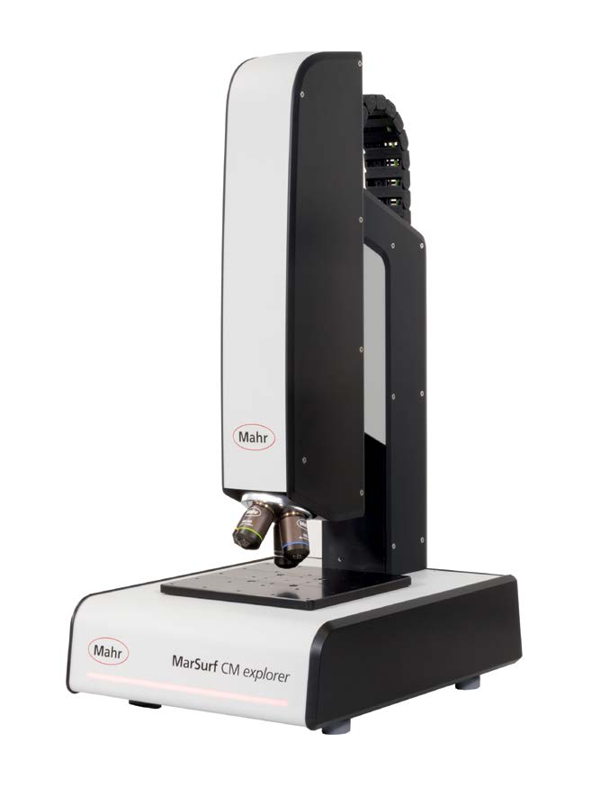
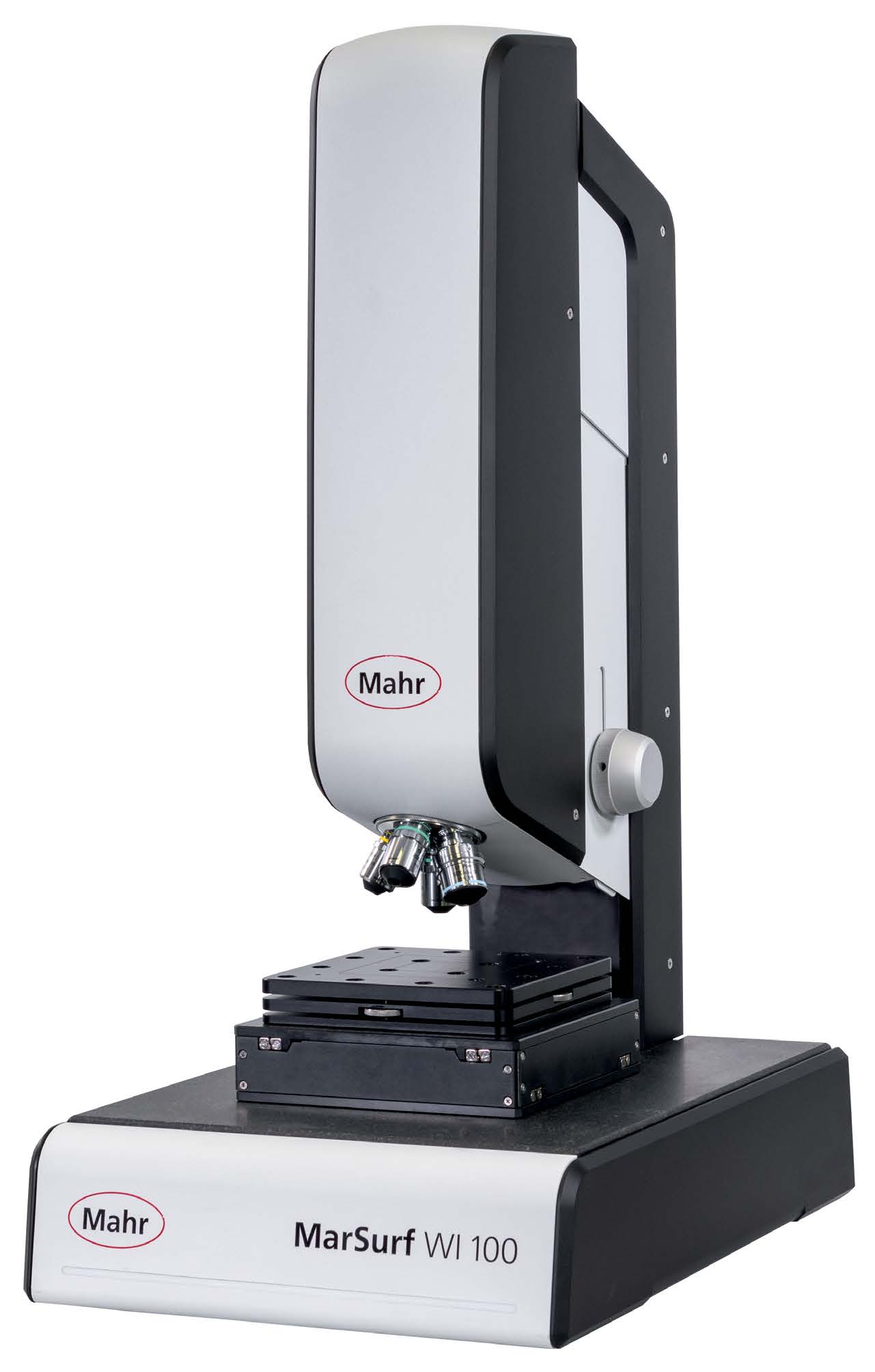
Mahr's earlier optical line used a dedicated instrument for each principle: the CM explorer, CM expert and CM select confocal systems, the WI 50 M, WI 50 and WI 100 interferometers, and the CP select and CL select profilometers. MarSurf 3D carries the same confocal and interferometry technologies onto the SX and GS platforms. Separate confocal and interferometer stations can be consolidated on one MS multisensor, which also adds focus variation.
MarSurf CM mobile
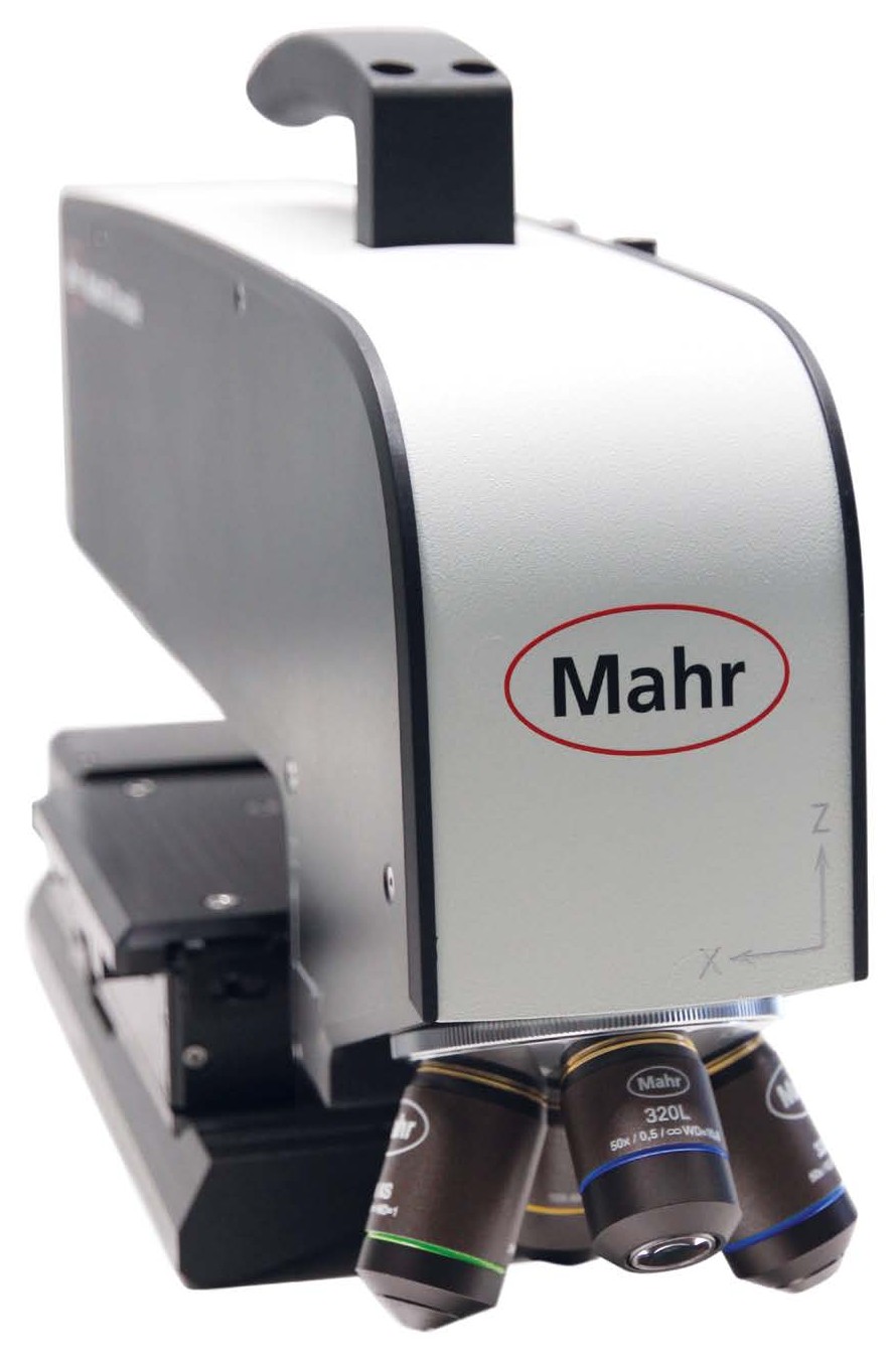
Portable confocal measuring system for parts that cannot be brought to a stationary instrument, such as rollers, car bodies and other large components. The system is placed on the part, which avoids cutting a sample for lab measurement.
It uses the same multi-pinhole confocal technology as the CM sensor. Motorized axes allow HD stitching of fields larger than one image, and a four-position objective revolver is standard. Mahr specifies the system for production environments as well as the lab.
| Measuring principle | Confocal, multi-pinhole |
| Dimensions | 417 × 136 × 234 mm (≈ 16.4 × 5.4 × 9.2") |
| Mass | 8.3 kg (≈ 18.3 lb) |
| Positioning volume x · y · z | 50 × 50 × 35 mm (≈ 2.0 × 2.0 × 1.4"), motorized |
| Piezo fine adjustment range | 350 µm (≈ .014") |
| Camera | 1200 × 1200 pixels, 1.44 million points per measurement, 16-bit HDR |
| Frame rate | 100 fps at full resolution |
| Objective holder | 4-position revolver standard |
| Color image | Optional |
| Roughness evaluation | ISO 4287, ISO 21920, ISO 25178 |
The 320XS and 160XS short-working-distance objectives (50× and 100×) are not available on the CM mobile.
Evaluation software
All sensors on the SX and GS platforms use the MarSurf3D evaluation software. Measurements taken with different principles on the MS multisensor are evaluated in the same program.
- Edit: form removal, region selection and filtering
- Evaluate: interactive roughness, geometry and tribology analysis
- Document: standardized reports with 2D and 3D images, profiles and tables
- Automate: saved evaluations rerun through QuickApps or batch processing
Specifying a system
The platform and sensor are selected separately. The following determine most configurations:
| Requirement | Determines |
|---|---|
| Whether the part can be brought to the instrument | SX or GS, or the portable CM mobile |
| Largest part and number of measuring sites | SX or GS, and table travel |
| Surface types: polished, rough, structured, steep-walled, or mixed | MS multisensor for mixed surfaces; CM or WI for uniform surfaces |
| Feature heights, nanometers to millimeters | Areal sensor (MS, CM, WI) or profilometer (CP, CL) |
| Tightest vertical tolerance | Standard or plus version with piezo drive |
| Spot checks or unattended series | Degree of automation, offset camera, GS continuous-duty setup |
| Transparent coatings or films | Layer-thickness capability (confocal, interferometry, CP or CL) |
Surface slope
Reflectivity is rarely the limiting factor, since the range covers 0.1% to 100%. Slope usually is. On a smooth surface, light reflects like a mirror. It returns into the objective only if the surface is close to perpendicular to the optical axis. Each objective collects light within a cone set by its numerical aperture (NA), and that cone sets the maximum flank angle it can measure. Higher-NA objectives measure steeper flanks over a smaller field.
Rough surfaces scatter part of the light back toward the objective, so real parts can often be measured at steeper angles than a mirror-smooth surface. For steep features, use focus variation on the MS multisensor (up to 86°), with HD stitching to cover the full area at full resolution.
Parameter selection
Areal parameters describe a surface differently from profile parameters such as Ra. When a drawing moves from profile to areal callouts, confirm that the specified parameter relates to the function of the surface (sealing, wear or adhesion) and that the evaluation area and filters are defined.
Where ICS fits
Have an application that could benefit from MarSurf 3D? Give us a call. We'll help you specify the right system for your application.
Mahr Inc.
With over 160 years of experience, Mahr is a global leader in precision metrology for quality control in measuring rooms, production, and development.
All Mahr Inc. lines →Questions about MarSurf 3d?
Tell us about your application and we'll point you to the right solution.