
844D - Plug Gages
844 D Plug Gages - The new Dimentron
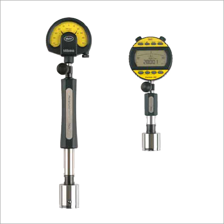
Bore measurement with a guide cylinder
The Marameter 844 D indicating plug gage was previously sold as the Dimentron plug. It is a two-point bore gage: two opposed carbide contacts are spring-loaded outward, and a carbide pin carries their radial movement to a dial comparator or digital indicator. The reading is the bore's deviation from the setting ring used to zero the gage.
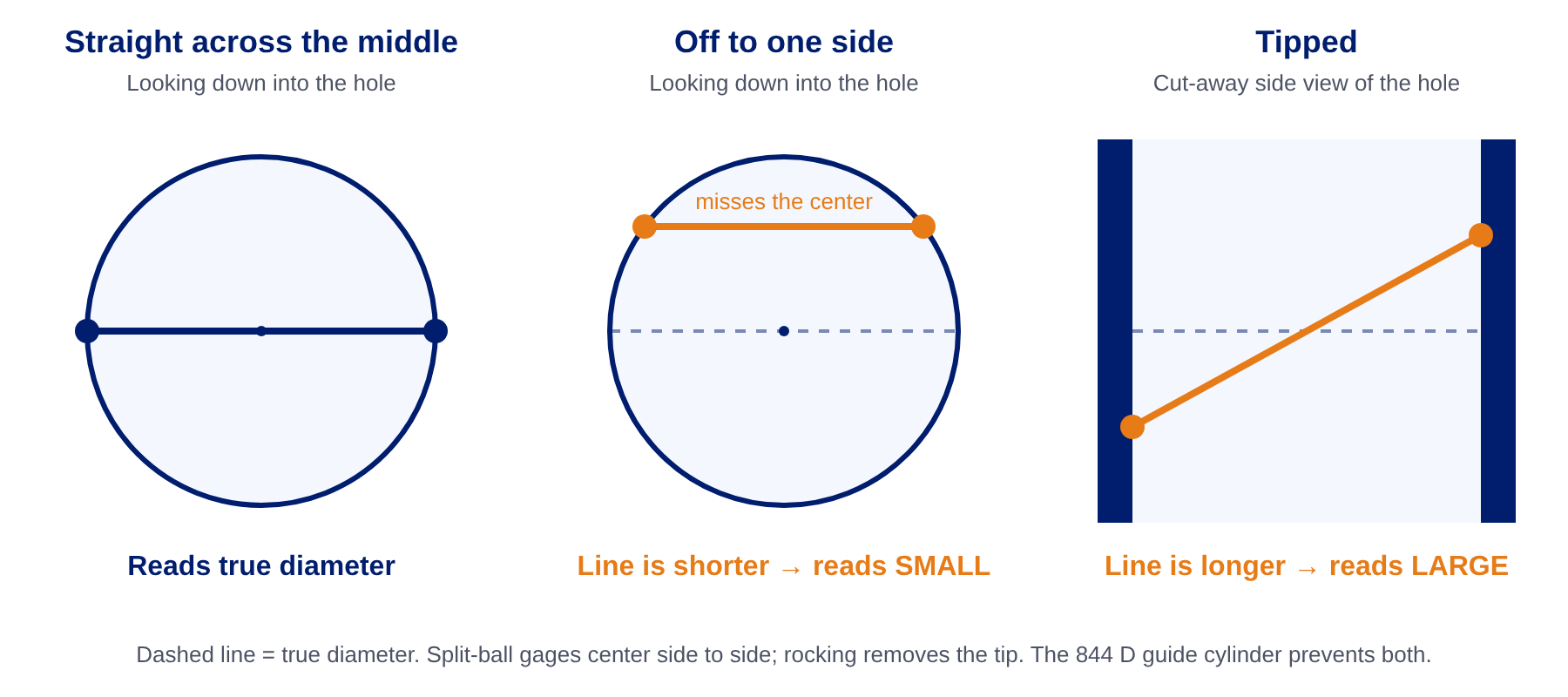
A two-point gage reads the true diameter only when its contacts sit straight across the middle of the bore and square to it. Off to one side, the contacts measure a line that misses the center, which is shorter than the diameter, so the gage reads small. Tipped, they measure on a slant from wall to wall, which is longer than the diameter, so the gage reads large.
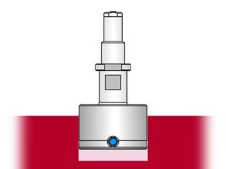
A split-ball gage centers itself side to side but can still tip, so the operator rocks it and takes the smallest reading, the reversal point. The 844 D handles both errors mechanically. Its guide cylinder is ground just under the bore size, so once it is in the hole it can neither slide sideways nor tip. There is no reversal point to find: the first reading is the reading.
- Measuring force comes from a built-in spring, so it does not vary with the operator.
- Diameter, roundness and conicity: one reading gives the diameter. Rotating the gage shows roundness deviation, and readings at several depths show conicity.
- Published performance: repeatability 1 µm (≈ .00004"); linearity deviation 1 % (min. 1 µm), 1.5 % on the DS types.
When to choose a plug gage
A plug gage suits the same bore checked over and over: production lots, in-process checks at the machine, or incoming inspection of one part number. Each gage is made to one nominal size, and no rocking technique is involved, so different operators get the same reading quickly. The trade-off is that a gage serves only that size. Many different bore sizes in small quantities mean many gages.
| Your application | Start with |
|---|---|
| One bore size, tolerance 10 µm (≈ .0004") or wider, open bore | 844 D |
| Tolerance under 10 µm | 844 D-HR (tighter guide-cylinder fit) |
| Tolerance zone wider than the 0.2 mm span | 844 D-M (0.4 or 0.6 mm span) |
| Through hole, or a bore in sheet or a thin wall | 844 DR |
| Diameter near the bottom of a blind hole | 844 DS; 844 DS-F for very short blind holes |
| Diameter at a specific depth on the drawing | 844 D-FD, or a depth stop on the standard gage |
| Soft or easily marked surfaces (aluminum, non-ferrous) | -C, -R or -D contacts (chrome, ruby, diamond) |
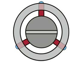
| Interrupted bore, or concern about lobed (out-of-round) form | 844 D-3 three-point gage, Ø 4–100 mm |
| Bores under Ø 2 mm, or many small sizes at low volume | 844 K split-ball probe set (Ø 0.95–20.6 mm) |
A two-point gage reads diameter across opposite contacts, so a bore with odd-numbered lobes (three, five) can read round. If that form error matters to the part, plan for the three-point 844 D-3 rather than relying on rotating a two-point gage. The 844 D covers Ø 2–200 mm; larger bores fall outside this family.
Three basic types by bore geometry
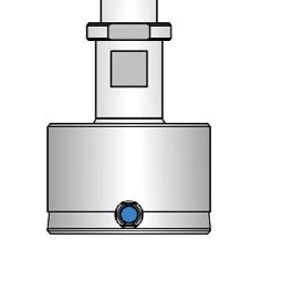
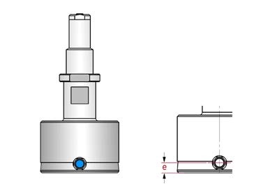
Every 844 D is made to one nominal bore size, with a measuring span of 0.2 mm (≈ .008"), or 0.15 mm below Ø 3 mm. Each has a hard-chrome guide cylinder and carbide measuring contacts. The types differ in where the contacts sit, measured as the distance e from the front face, and in how much guide length supports the gage.
844 D
Ø 2–200 mm (≈ .079–7.87"). e = 1.5–4 mm. For fast checks of precise bores in general work.
Choose it when the bore is open and the characteristic is not right at an edge or bottom.
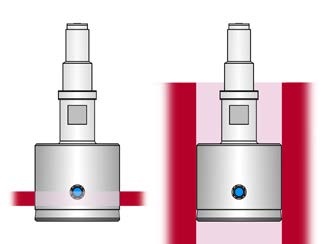
844 DR
Ø 4–200 mm. e = 6–10 mm. An extended guide cylinder runs past the contacts, so the gage stays aligned in through holes and in parts thinner than the guide.
Choose it when the bore is in sheet or a thin wall, or must be measured from the edge of a through hole.
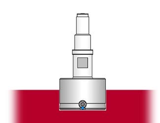
844 DS
Ø 2–200 mm. e = 0.7–1.2 mm. The contacts sit close to the front face. Linearity deviation is 1.5 % (min. 1 µm).
Choose it when the diameter must be checked close to the bottom of a blind hole.
Variants by measuring problem
Variants change one property of the basic type: the contact material, the contact position, the measuring span, the guide-cylinder fit or the number of contacts.
| Variant | What changes | Types and range | Use it for |
|---|---|---|---|
| -C | Hard-chrome contacts | D, DR, DS: 8–200 mm | Sensitive non-ferrous and aluminum surfaces |
| -R | Ruby-tipped contacts | D, DS: 3–200 mm; DR: 4–200 mm | Very sensitive non-ferrous and aluminum surfaces |
| -D | Diamond-tipped contacts | D, DR: 8–200 mm | Very sensitive surfaces of soft non-ferrous metals and aluminum |
| -FD | Front distance e to customer specification | D: 2–200 mm; DR: 4–200 mm | Measuring closer to the bottom, or at a defined position |
| -M | Measuring span 0.4 mm (Ø 3–7) or 0.6 mm (Ø >7) | D, DS: 3–200 mm; DR: 4–200 mm | Wider tolerance zones |
| -HR | Guide cylinder held to a tighter tolerance | D, DS: 3–200 mm; DR: 4–200 mm | Tolerance zones under 10 µm |
| DS-F | Front chamfer only, no centering groove | DS: 2–200 mm | Very short blind holes |
| -3 | Three contacts at 120°; linearity deviation 2 % (min. 1 µm) | D, DR: 4–100 mm | Interrupted bores and polygonal (odd-lobed) form errors |
Tolerance under 10 µm? Guide-cylinder clearance is the limit
Mahr rates the standard 844 D for tolerance zones of 10 µm (≈ .0004") and more. Against the 1 µm repeatability, that is a 10:1 ratio. The guide cylinder has to clear the bore, and the remaining gap lets the gage shift radially and axially. The HR version is ground closer to nominal, which cuts that gap by 10 µm at every size:
| Bore Ø | Guide cylinder, standard | Guide cylinder, HR |
|---|---|---|
| 3–20 mm | −15 / −25 µm | −5 / −15 µm |
| >20–60 mm | −20 / −30 µm | −10 / −20 µm |
| >60–130 mm | −25 / −35 µm | −15 / −25 µm |
| >130–200 mm | −35 / −45 µm | −25 / −35 µm |
For example, an H5 bore at Ø 25 mm has a 9 µm (≈ .00035") tolerance under ISO 286, which puts it in the HR range. An H7 bore at Ø 40 mm (25 µm, ≈ .001") is well within the standard gage's range.
Specifying a gage and building the setup
Because each 844 D is made to one bore, an order states three things: the order number (which fixes the type, variant and size band), the nominal bore diameter, and the bore tolerance as an ISO fit or numeric limits. For example, an 844 D for Ø 34.5 mm H8, or an 844 DR for Ø 74.55 mm +0.05 / −0.03 mm.
The plug gage screws onto a holder that carries the indicator. Extensions, a 90° attachment and depth stops thread in between. Mahr shows three typical builds:
| Task | Stack, indicator to bore |
|---|---|
| Standard check | Comparator, 844 Dg holder, plug gage |
| Defined measuring depth | Comparator, 844 Dg holder, 844 Dv extension, 844 Dt-3 depth stop, plug gage |
| Side-entry bore at a defined depth | Comparator, 844 Dg holder, 844 Dw 90° attachment, plug gage, 844 Dt-R stop ring |
Holders, reach and measuring depth
- 844 Dg holders take Ø 8 mm indicator shanks and M6 × 0.75 or M10 × 1 plug gages, in lengths from 109 to 249 mm.
- 844 Dga adds a lifting lever that retracts the contacts. It eases a DS gage into a blind hole and is recommended for small, sensitive bores.
- 844 Dg-XL is the heavy holder for plug gages from Ø 60 mm, especially on long Ø 18 mm extensions.
- 844 Dv extensions run from 48 to 1000 mm (≈ 1.9–39.4"). 844 Dw turns the measuring axis 90° for side bores and for checks in a lathe or grinder.
Depth stops set a repeatable measuring depth and keep the gage from tilting on entry: the 844 Dt-R ring clamps on the guide cylinder (Ø 3–105 mm). The Dt-S disc (Ø 16–40 mm), Dt-B bridge (Ø 16–160 mm) and Dt-3 three-point stop (Ø 20–150 mm) clamp on the holder or extension shank.
Setting ring and temperature
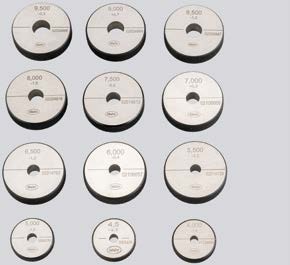
The 844 D is zeroed on a setting ring at the nominal size, so the reading is only as good as the ring. It also depends on how closely the ring and the part share a temperature. A steel ring and a steel part at the same temperature grow together, and the error largely cancels.
Aluminum does not cancel. Take an aluminum bore (≈ 23 µm/m·K) checked against a steel ring (≈ 11.5 µm/m·K), both at 25 °C instead of the 20 °C reference. At Ø 100 mm the differential growth is 11.5 µm/m·K × 0.100 m × 5 K = 5.75 µm (≈ .00023") (calculated). That is more than five times the gage's repeatability.
Indicator and data path
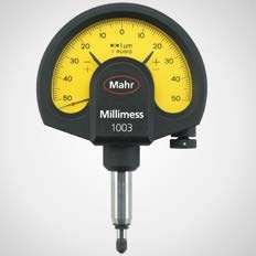
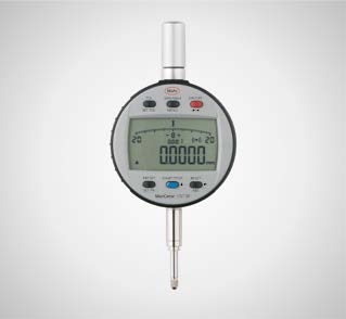
Indicator resolution sets the smallest step you can see. It does not change the gage's 1 µm repeatability. Choose the indicator for the tolerance zone and for where the data has to go.
| Indicator | Resolution | Range | Role |
|---|---|---|---|
| Millimess 1002 | 0.5 µm | ±25 µm | Analog comparator, tight tolerance zones |
| Millimess 1003 | 1 µm | ±50 µm | Analog comparator, general use |
| 1086 R / Ri | 0.5 µm | 12.5 mm | Digital indicator for processing measured values |
| 1086 R-HR | 0.1 µm | 12.5 mm | Digital, finest display step |
| P2004 M + C 1200 M | — | ±2 mm probe | Inductive probe and compact amplifier in the 844 Dge holder, with fine adjustment |
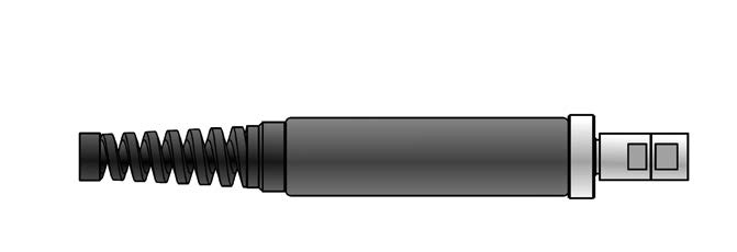
Below Ø 2 mm, or many sizes: 844 K split-ball probes
The 844 K covers Ø 0.95–20.6 mm (≈ .037–.811") with interchangeable split-ball probes on one holder. Its repeatability (1 µm) and linearity deviation (1 % min. 1 µm, 2 % on Ø 1–1.4 mm probes) match the 844 D.
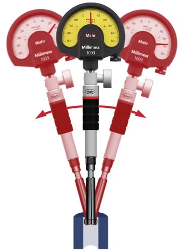
The trade-off is centering. The two halves of the split ball expand equally, so the contacts center side to side and land on a diameter rather than a chord. The short ball can't hold the probe square to the bore axis, though. The operator rocks the gage through the axis, and the smallest reading, the reversal point, is the one taken square to the bore. A 1087 BR/BRi digital indicator records that minimum with its MIN function, and the 844 KM measuring stand removes the rocking step altogether.
Each probe covers a band rather than one size: 0.2 mm (Ø 1–1.4), 0.4 mm (Ø 1.75–3.75), 0.6 mm (Ø 4–9.5) or 1.2 mm (Ø 10–20). Cased sets cover the full range in five groups. The probes come in hard chrome (844 K), DLC-coated (844 KC) and blind-hole (844 KS) versions. The 844 Kgz holder takes 3/8" indicator shanks.
| 844 D plug gage | 844 K split-ball probe | |
|---|---|---|
| Diameter range | 2–200 mm | 0.95–20.6 mm |
| Centering | Guide cylinder: centers and aligns | Split ball: centers side to side, not in tilt |
| Reversal point | Not required | Found by rocking, or with the 844 KM stand |
| Range per gage | One bore size; 0.2 mm span | 0.2–1.2 mm band per probe |
| Contact surface options | Carbide, hard chrome, ruby, diamond | Hard chrome, DLC |
| Best fit | One bore size checked in volume, independent of operator technique | Small bores in many sizes, one instrument across a range |
Where ICS fits
Industrial Channel Solutions is a manufacturers' representative. We match your application to the right measuring tools. For Marameter plug gages, the selection depends on:
- Diameter and tolerance: the nominal bore, the tolerance zone and the gage ratio you need (standard, HR or -M span)
- Bore geometry: open, through, blind, short, interrupted or thin-walled, and where along the bore the characteristic sits
- Material and finish: steel, aluminum or soft non-ferrous metals, and how sensitive the surface is
- Access: bore depth, side bores, or checks in the machine
- Data path: visual check, or values sent on for processing
- Number of sizes: a dedicated 844 D per bore, or 844 K probes for small bores across many sizes
From those inputs we recommend one measuring setup: the plug gage type and variant, holder, indicator, extensions and depth stops.
Mahr Inc.
With over 160 years of experience, Mahr is a global leader in precision metrology for quality control in measuring rooms, production, and development.
All Mahr Inc. lines →Questions about 844D - Plug Gages?
Tell us about your application and we'll point you to the right solution.