
Digimar - Height Gages
Shop floor, manual gages to motorized 2D height gage systems.
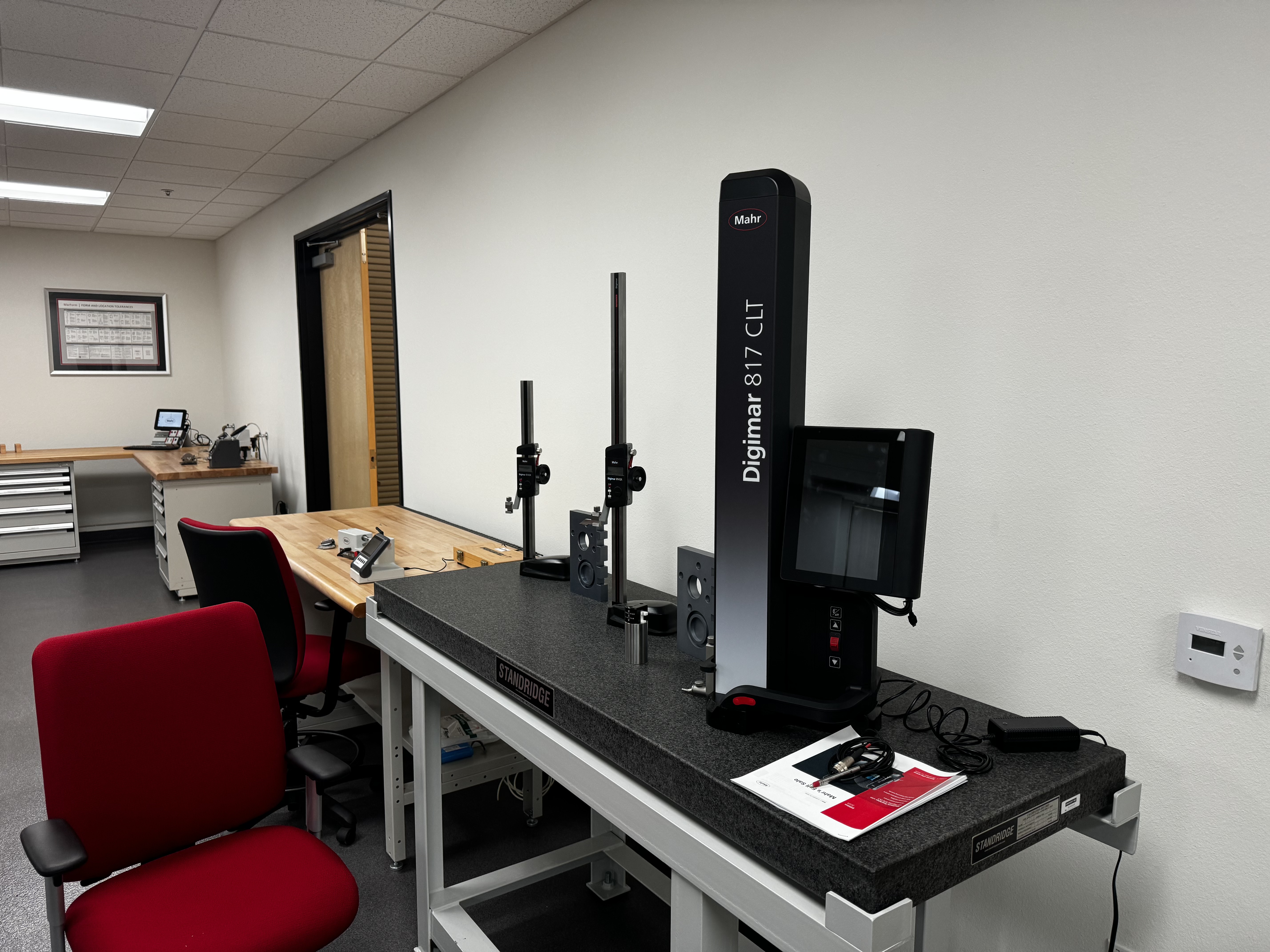
Single-axis measurement from a datum plane
A height gage measures along one axis, perpendicular to a granite surface plate that serves as the datum. Each reading is the distance from that plane to a probed point: a face, a step, or the upper or lower extreme of a bore. Feature-to-feature distances, bore and shaft diameters, center positions and symmetry are all calculated from those readings. On prismatic parts dimensioned from a datum face, that covers much of the inspection plan without tying up a CMM.
On a manual gage, the largest contributor to measurement error is probing. The operator applies the contact force by hand and finds a bore's reversal point by sweeping the probe across it. A motorized gage controls both. The slide drives the probe onto the surface at a defined measuring force (1.0 ± 0.2 N on the 817 CLT), and the dynamic probe system captures the reversal point automatically. Repeatability then depends on the instrument rather than on who is operating it.
Measuring functions
- Height and distance from the plate datum or from additional zero points set on the workpiece.
- Bore and shaft diameter and center, from reversal points probed top and bottom. The motorized models capture them automatically; the manual models use MAX/MIN memory.
- Web width and groove spacing, with the web or groove center, plus calculated distance and symmetry (motorized models).
- Perpendicularity and straightness, read by a digital comparator connected through the slide (816 CLT, 817 CLT).
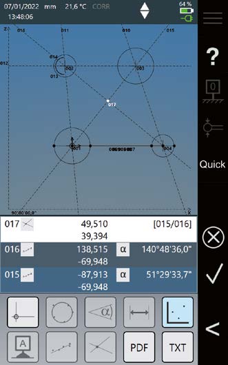
- 2D evaluation of bore positions, distances and angles (817 CLT).
- Scribing, with the measuring head clamped (814 N, 814 G).
Three instrument classes
The Digimar range splits by drive and probing method: a manual head with an inductive measuring system, or a motorized slide reading an optical linear encoder. That choice sets the error limit, the repeatability, and the evaluations the controller can run.
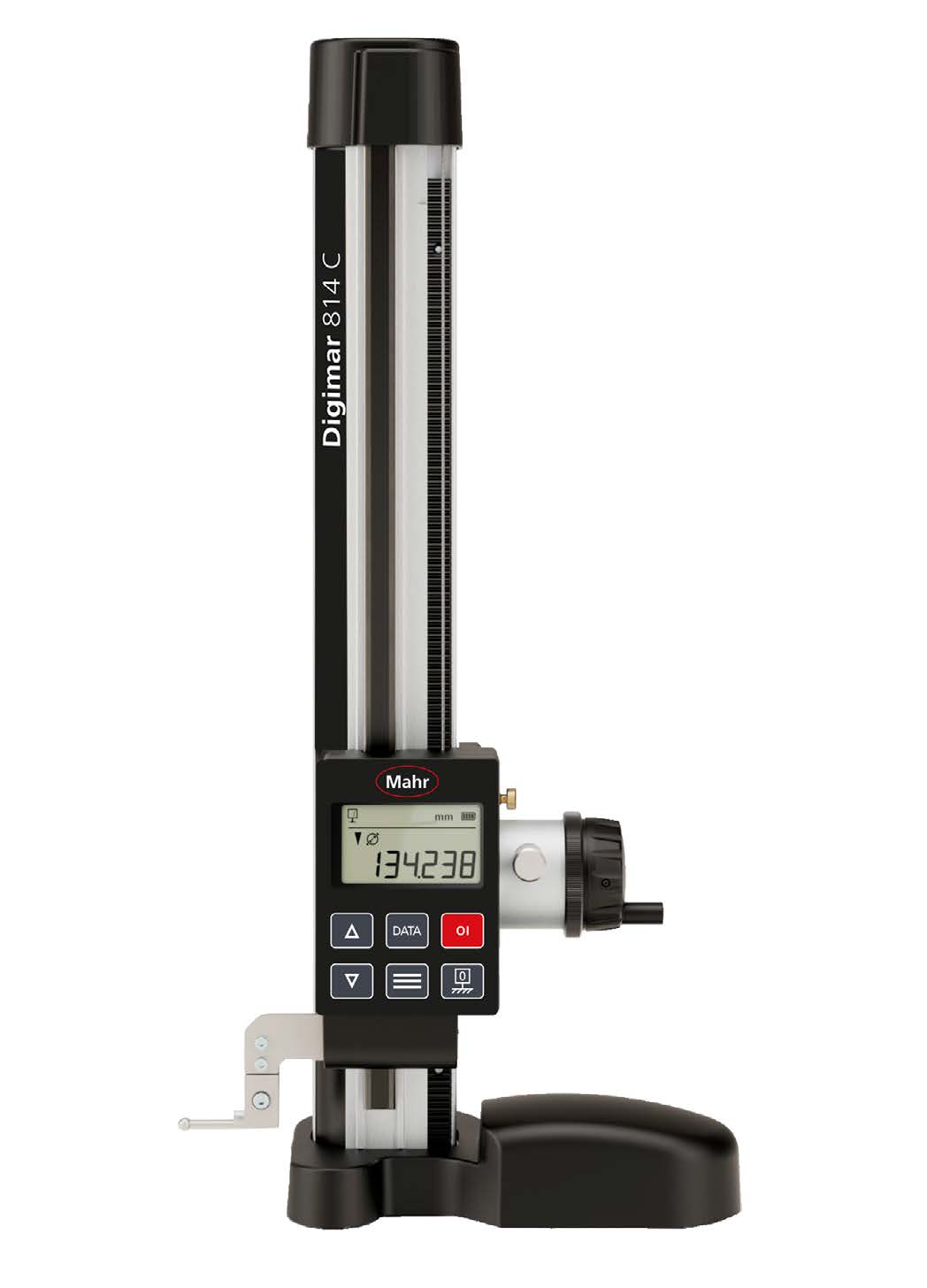
Digimar 814 C, 814 N, 814 G
A handwheel or crank positions the head. The head applies a constant measuring force, upward or downward, and reads an incremental inductive system. All three are battery powered.
Choose it when tolerances are in tens of microns: heights, step distances, diameters by MAX/MIN, layout and scribing.
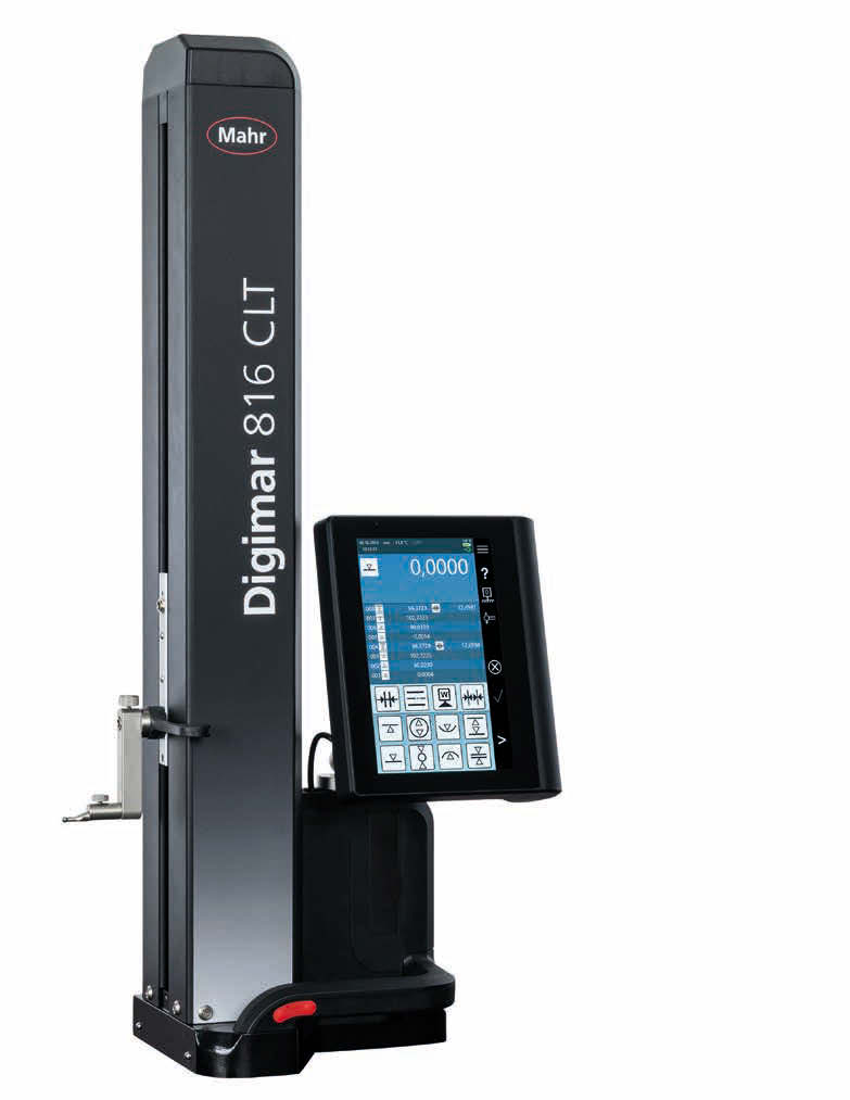
Digimar 816 CLT
A motorized slide carries a dynamic probe system and reads its position from an optical linear encoder. An air bearing is used for repositioning the gage on the plate. Error limit 2.0 + L/400 µm; repeatability 1 µm on planes and 2 µm on bores.
Choose it when features are held to a few microns, several operators share the gage, and records are needed at the plate.
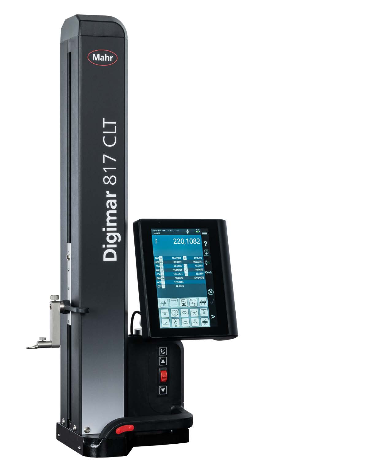
Digimar 817 CLT
The measuring principle is the same as the 816 CLT, with an error limit of 1.8 + L/600 µm and repeatability of 0.5 µm on planes and 1 µm on bores. Ranges go to 1,000 mm. The controller adds 2D evaluation, a cone function, double-probe measurement and an ISO tolerance table.
Choose it when you are measuring bore patterns, tapers or tall parts, or features where repeatability takes most of the measurement-uncertainty budget.
Error limit by class
The error limit of the motorized gages depends on length: a fixed term plus a term proportional to the measured length L. At L = 300 mm:
The 814 value is the stated error limit of the 0–320 mm model. The 816 CLT and 817 CLT values are calculated from Mahr's formulas.
Before choosing a class, apply your quality system's gage-to-tolerance ratio to these figures. At 4:1, the 814's 20 µm supports a tolerance band of about 80 µm (.003"), and the 817 CLT's 2.3 µm supports about 9 µm (.00036"). Going from manual to motorized improves the error limit by a factor of 7 to 9. Between the two motorized gages, the error limits differ by only 0.45 µm at 300 mm and 0.7 µm at 600 mm. The bigger difference is repeatability, which is half as large on the 817 CLT for both planes and bores.
816 CLT or 817 CLT
- Motorized measuring slide with dynamic probe system
- Optical linear encoder
- Measuring head guided on precision ball bearings
- Air bearing actuated from the handles
- Integrated temperature sensor for compensation
- Resolution selectable down to 0.0001 mm / .00001"
- Comparator port in the slide for perpendicularity and straightness
- MarConnect over 3× USB 2.0 or wireless; PDF records generated on the gage
- Rechargeable battery, up to 14 h
- Repeatability 0.5 µm on planes and 1 µm on bores (816 CLT: 1 µm and 2 µm)
- Error limit 1.8 + L/600 µm (816 CLT: 2.0 + L/400 µm)
- 0–1,000 mm (0–40") measuring range option
- 2D measuring and evaluation functions
- Auto distance, double-probe measurement, cone function, third zero point
- Integrated ISO tolerance table; programs by drag-and-drop or teach-in
- Thumbwheel, plus quick-measurement keys that detect surfaces and bores
The 816 CLT has a simpler interface instead of the 817's evaluation functions. Its touch keys are extra-large, and it has no 2D mode or tolerance table. That suits gages shared across shifts for routine height and bore work. The 817 CLT is justified when the part needs 2D, cone or double-probe evaluation, a range over 600 mm, or the tighter repeatability.
| 816 CLT | 817 CLT | |
|---|---|---|
| Measuring range | 350, 600 mm (14", 24") | 350, 600, 1,000 mm (14", 24", 40") |
| Error limit, L in mm | 2.0 + L/400 µm | 1.8 + L/600 µm |
| Repeatability, planes | 1 µm | 0.5 µm |
| Repeatability, bores | 2 µm | 1 µm |
| Perpendicularity error, by range | 5 µm, 8 µm | 5 µm, 6 µm, 10 µm |
| Weight, by range | 22 kg, 26 kg | 22 kg, 26 kg, 29 kg |
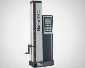
Running an 816 CL?
The 816 CL is the keypad-and-LCD predecessor. Its measuring head runs on stainless steel guideways rather than ball bearings. Error limit 2.8 + L/300 µm; repeatability 2 µm on planes and 3 µm on bores; perpendicularity error 15/20 µm; a 99-value memory with Opto RS-232C, USB or wireless output. Moving to the 816 CLT halves plane repeatability, cuts perpendicularity error to 5/8 µm, and replaces the value memory with complete PDF records produced on the gage.
The manual models
The 814 N and 814 G share one head: an incremental inductive measuring system on a ball-bush guide, with the display built in. Functions are preset and zero at any position, MAX/MIN for reversal points, MAX–MIN for flatness and concentricity checks, and a tolerance limit for one characteristic. Measuring force is constant at 3 N in either direction.
| Measuring range | 0–320 mm or 0–620 mm (0–12.6" or 0–24.4") |
| Resolution | 0.001, 0.01 mm / .00005", .0005" |
| Error limit | 20 µm (320 mm) or 30 µm (620 mm) |
| Perpendicularity error | 20 µm (320 mm) or 30 µm (620 mm) |
| Data and power | Opto RS-232C or wireless; CR 2032 lithium cell |
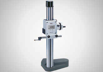
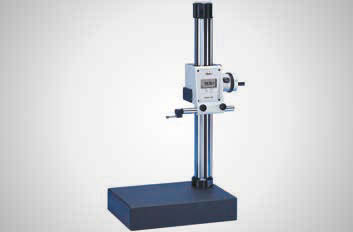
The Digimar 814 C is the newest manual model. It comes in 300 mm and 600 mm ranges, on a steel base or a granite table. A handwheel with fine adjustment positions the slide, and the measuring force is constant. It measures in both directions for diameters and distances, and it sends data over USB to MarCom software.
Operator interface
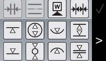
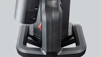
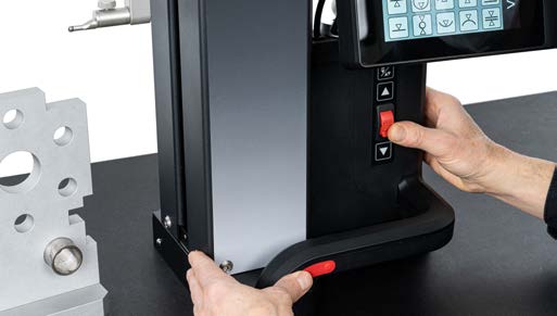
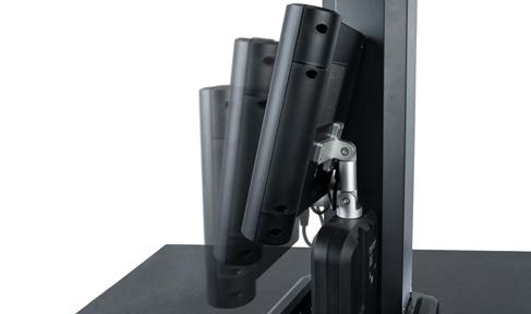
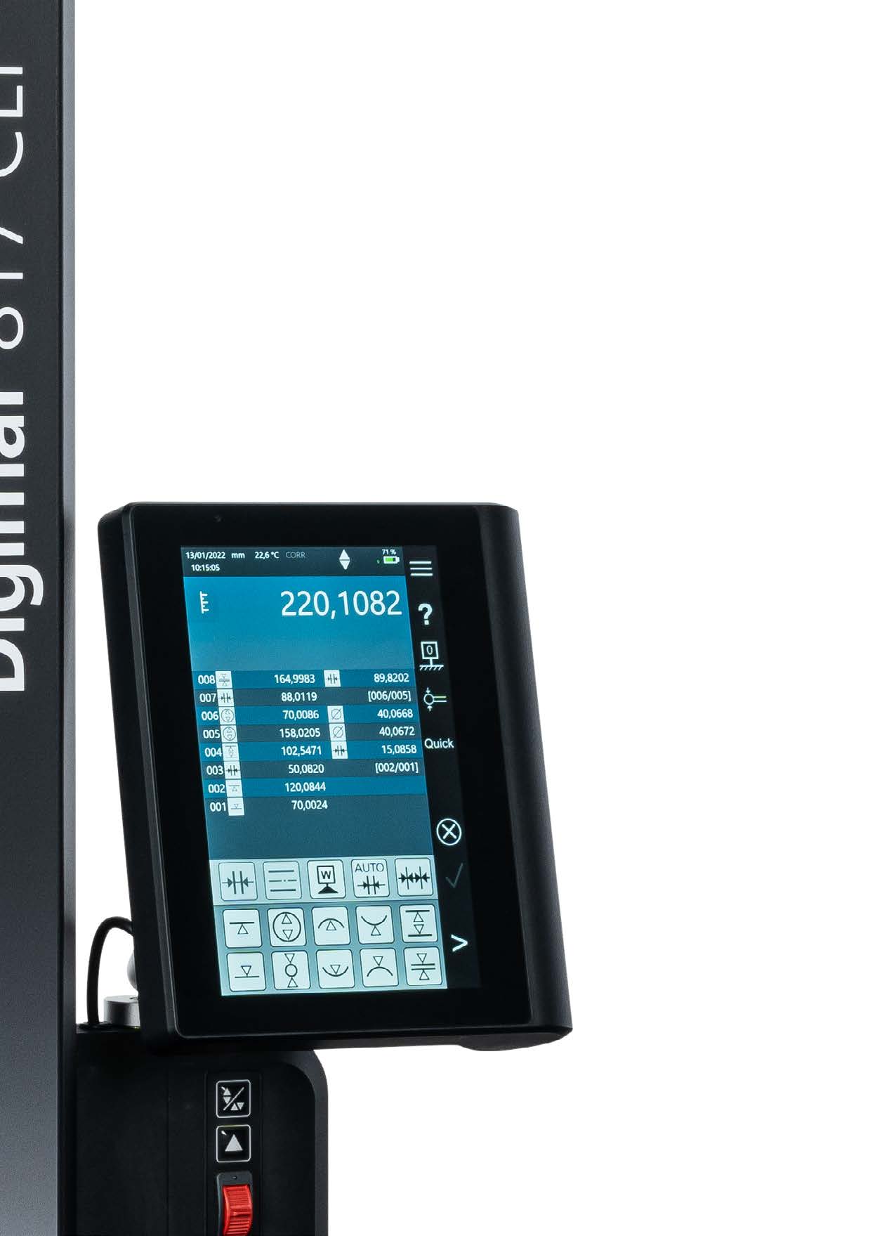
Because probing is automated, the operator's remaining tasks are positioning the gage, selecting the measuring function, and reading or recording the result. The interface sets how much time each step takes and how often the wrong function gets selected. The 816 CLT uses a reduced set of extra-large keys. The 817 CLT adds a thumbwheel and side keys for positioning the slide, and its display adjusts to the operator's working position.
Measurement conditions and setup
Datum and temperature
The surface plate is the datum, so its flatness error adds directly to every reading. Specify and calibrate the plate together with the gage. Granite plates of 1,000 × 630 mm and 1,200 × 800 mm are available with open underframes.
Dimensional measurements are referenced to 20 °C, which is also the working temperature these gages are specified at. They operate from 10 to 40 °C, up to 65% relative humidity, non-condensing. Steel expands about 11.5 µm per metre per kelvin, so a 300 mm steel part 2 K above reference reads about 7 µm long. That is three times the 817 CLT's error limit at that length. The integrated temperature sensor compensates the instrument, but parts still need time to soak to room temperature before measurement.
Probe selection
Bore and shaft diameters depend on the probe constant, which is calibrated with the 817 eb setting block supplied with the CL and CLT gages. The constant is retained after the gage is switched off. Match the probe geometry to the feature:
| Probe | Application |
|---|---|
| Spherical anvil, carbide or ruby, ø 1–10 mm | Planes, bores and shafts; general use |
| Disc anvil, ø 15 mm | Groove diameters, tapered diameters |
| Cylindrical anvil, ø 10 mm, on pivoting carrier 817 h5 | Tapers; features with small contact surfaces |
| Conical anvil (MKe 30, MKe 8) | Hole center location, especially in thin-walled parts and sheet |
| Depth probe TMT 120 / TMT 120 S; probe shoe | Blind-hole depth, groove spacing, recesses |
| Extended carrier 817 h2 | Features at increased measuring depth |
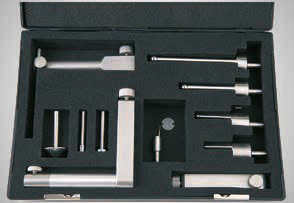
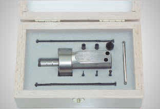
Three kits cover the CL and CLT gages. The 817 ts1 includes depth, disc, conical and cylindrical probes, an M2 stylus holder, and an 817 h4 8 mm carrier with four spherical anvils. The 817 ts2 is the same kit without the 817 h4 carrier and spheres. The 817 ts3 is for small parts and fine grooves, recesses and bores, and mounts on the 817 h4 carrier.
Perpendicularity and straightness
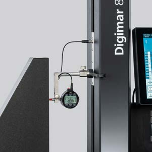
On the 816 CLT and 817 CLT, a Millimess 2000 W or 2001 W digital comparator mounts in the 817 h3 carrier and connects to the slide with the DK-M1 cable. The gage then measures and documents perpendicularity and straightness automatically. The result is recorded with the rest of the measuring record, so nobody has to write down an indicator reading.
Data output and traceability
The CLT models generate complete PDF measuring records on the instrument, with no PC involved. Results can also be saved as TXT. Data leaves over the MarConnect interface, either 3× USB 2.0 or wireless through an i-Stick receiver. The MarConnect duplex link also transmits the instrument ID, so each result can be traced to the gage that produced it. MarCom Professional, a free download, collects the data on a PC.
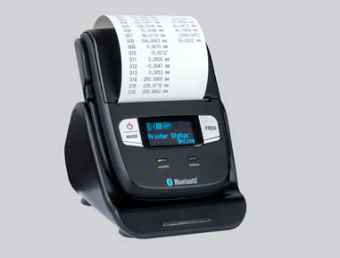
Decide where results go (an SPC system, a network share, or a printed record from the DP-B1 Bluetooth printer) before specifying the gage. That decides which interface hardware and software you need.
Application help
ICS is a manufacturers' representative. Our job is to match your application to the right measuring tools. Send us a print, or tell us about the part, the features you need to check and the tolerances involved, and we'll recommend a height gage, probes and accessories that fit the work.
Mahr Inc.
With over 160 years of experience, Mahr is a global leader in precision metrology for quality control in measuring rooms, production, and development.
All Mahr Inc. lines →Questions about Digimar - Height Gages?
Tell us about your application and we'll point you to the right solution.